A Race tracks not a Race track without a Starting Light and a Results display. So this page will show you how to build and set up your displays in most any scale.
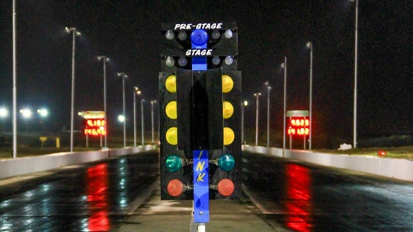
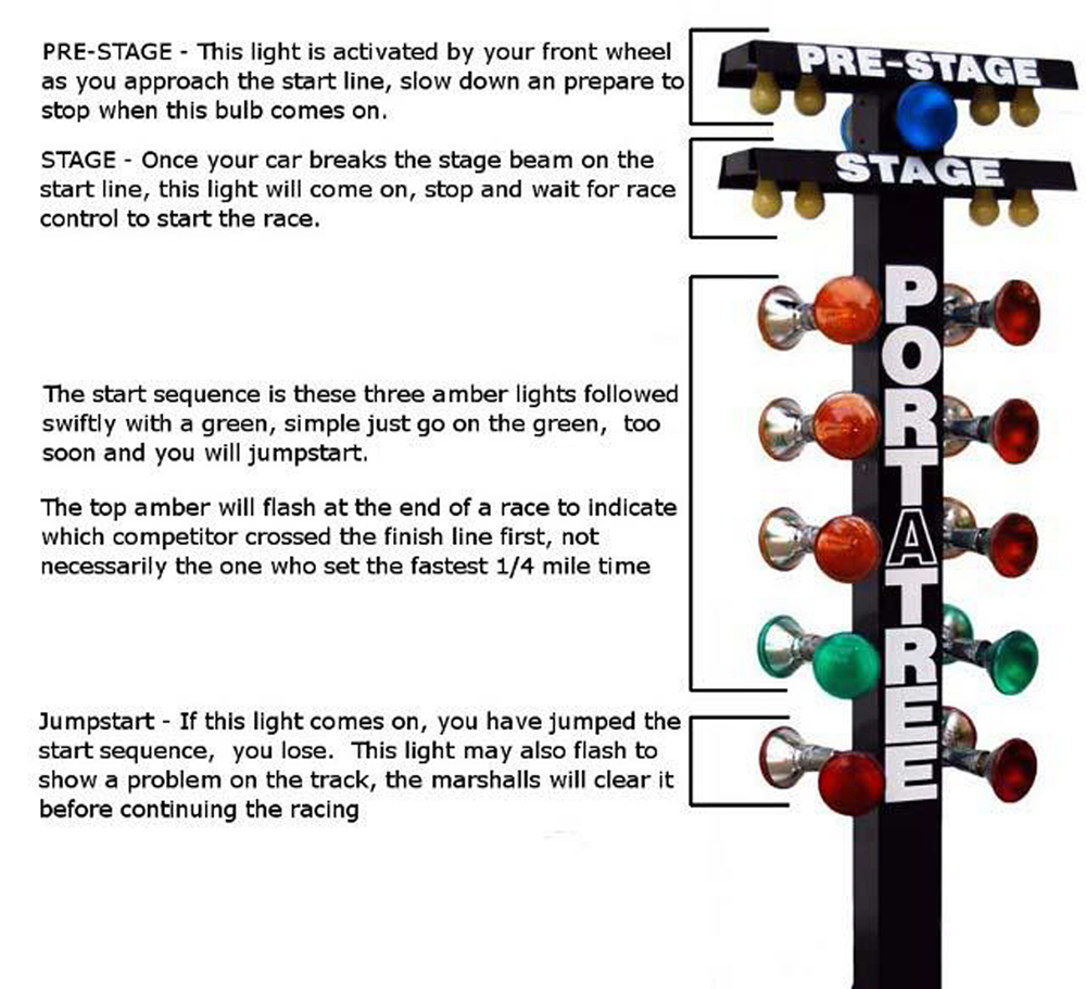
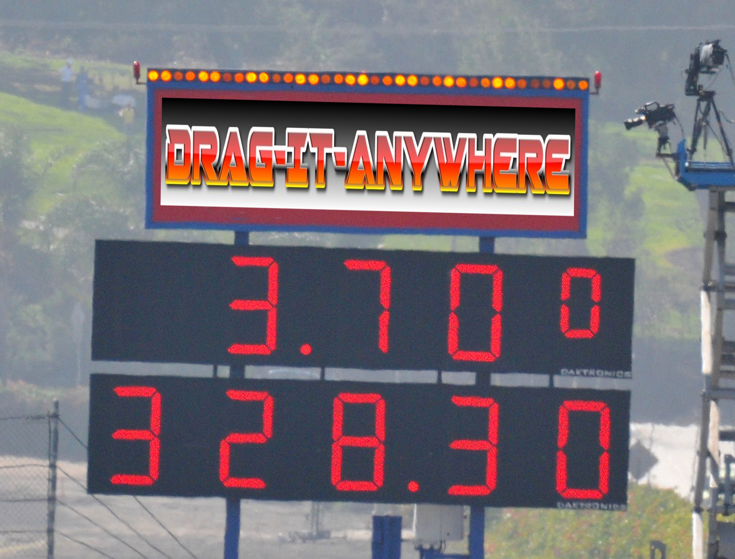
This section will show you how to install our DIA Starting Tree and Lap Racing Displays
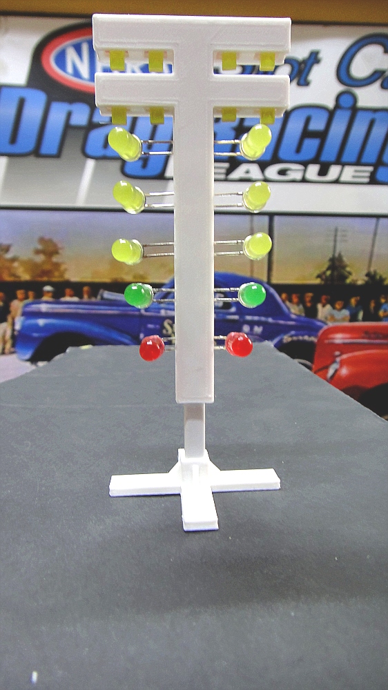
DRAG RACING CHRISTMAS STARTING TREE INSTALLATION
Just follow the install pictures and descriptions
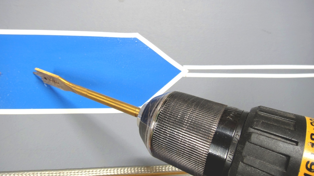
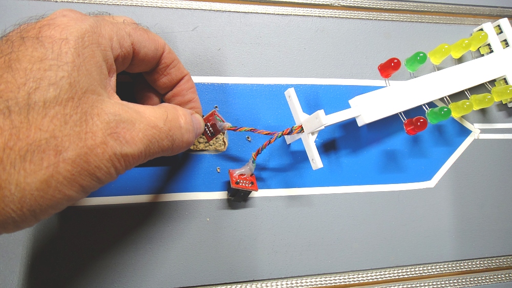
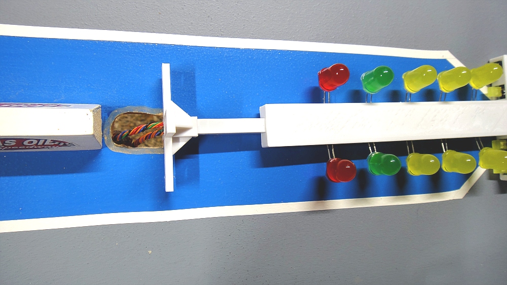
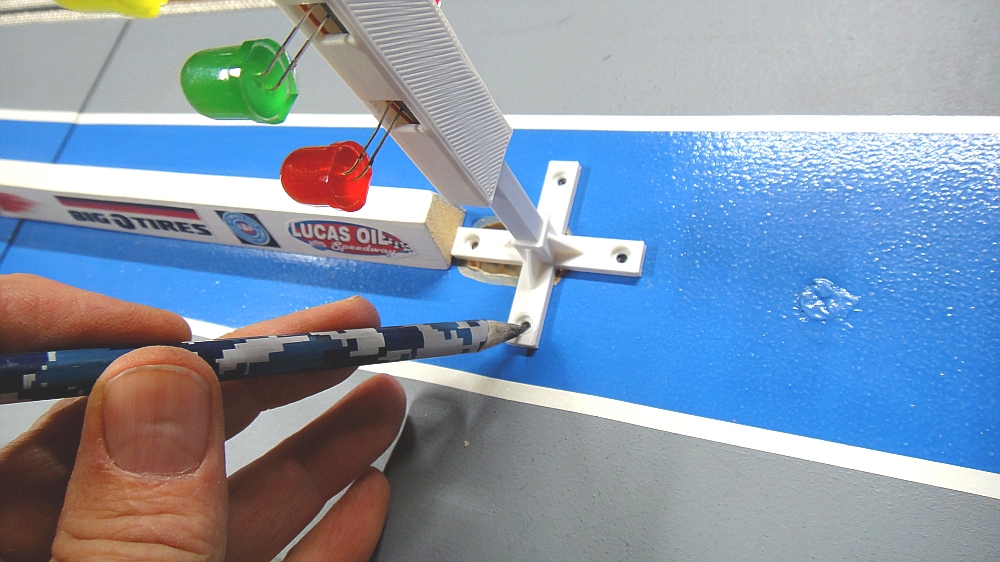
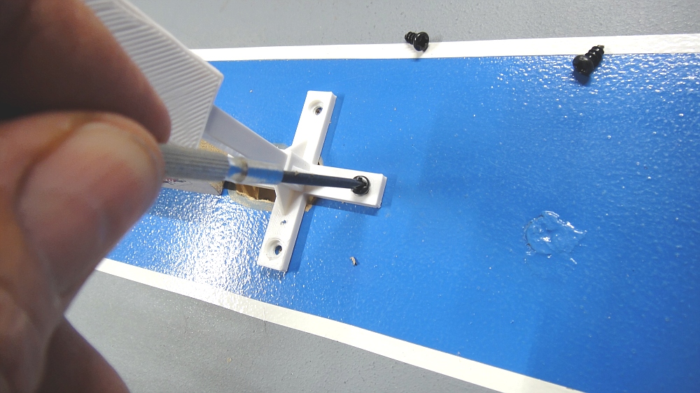
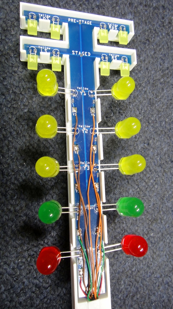
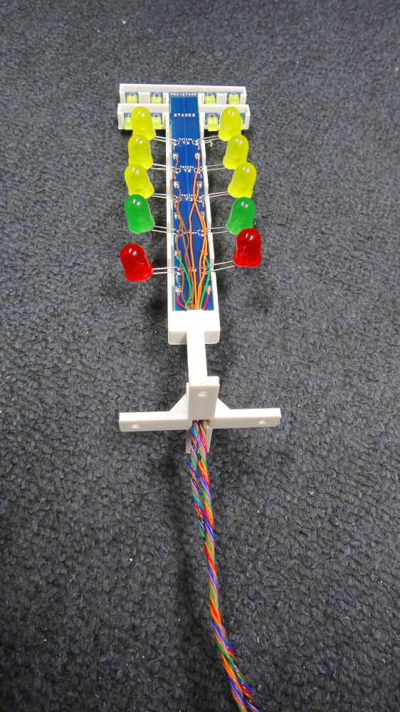
First locate where you wish to place your STARTING TREE. Next, using a 5/8″ drill bit, drill a hole thru your track material. Next carefully push the trees wiring system thru the hole. Now set your tree in position and mark the mounting holes with a pencil. Now take a drill and pre-drill the holes but not to big !
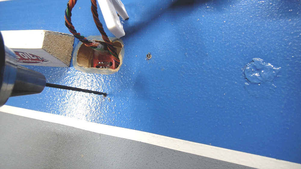
Now drill the hole for the screws. Mount your Starting Tree and with the provided screw tighten down carefully.
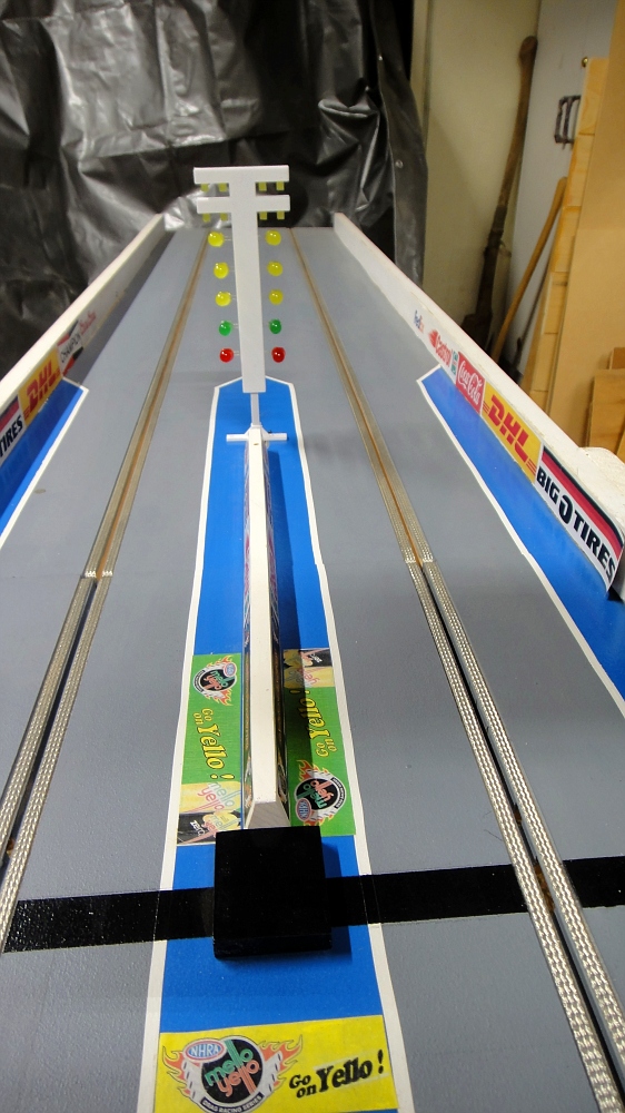
Your Starting Tree in now mounted. Time to hook up the Data cables.
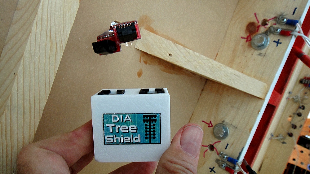
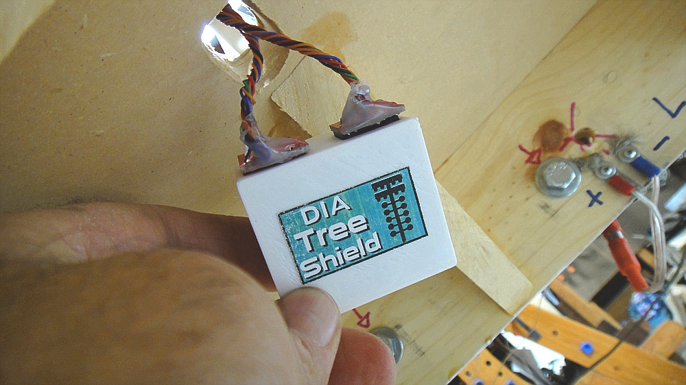
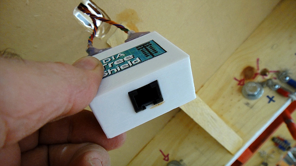
In order for the Tree to work properly, you must now plug it into the DIA Tree Shield Module. Plug the Left & Right side Tree wires into the back of the shield. You will connect a 6C6P Data cable to the Front and run it to the main DIA unit into the TREE PORT CONNECTION. If during a test. the lights for the Left and Right are reversed just switch the plugs.
You are now ready to Rock Baby !
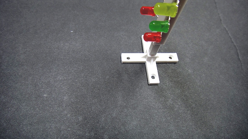
The same process will apply with the smaller 1/62 scale Tree into your layout
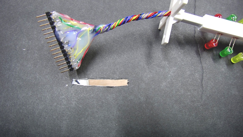
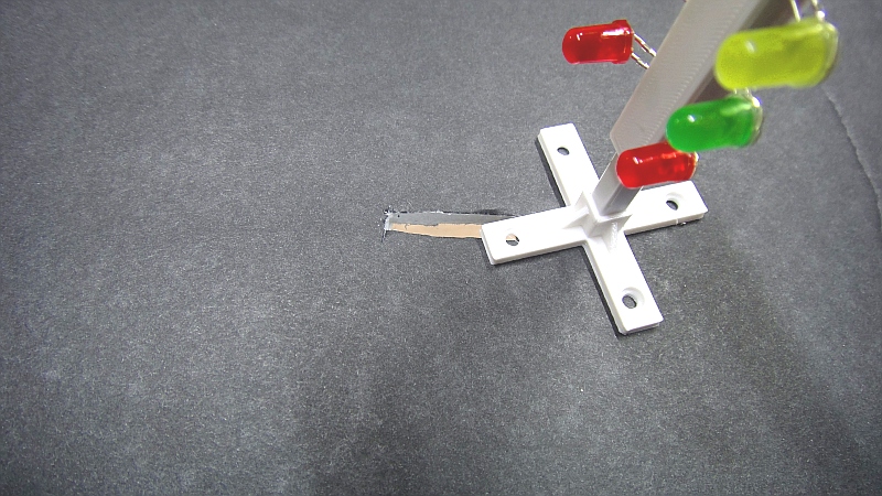
Cut a 8mm x 38mm Slit in your layout to allow the wiring Harness to slip thru.
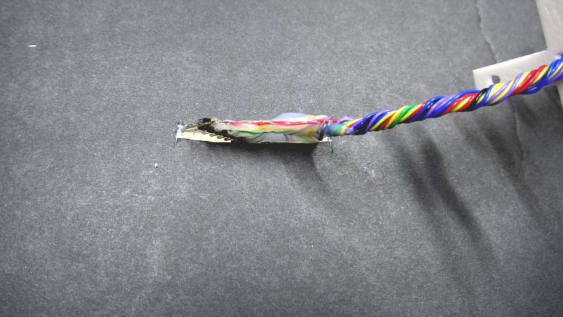
Then carefully run wire harness thru and under layout.
Cover slit with the Tree Base and screw in to secure. Plug wires into the DIA Tree Shield for 1/64 Scale and your ready to race !!!

Placement of Sensors on Track
In order for the DIA unit or any Speed trap system to correctly capture the speed of a passing vehicle, the sensors MUST be aligned at a correct distance apart !
The Guide below indicates the correct distance for the 1000ft to Finish Sensors based on what Scale you select and the TRACK LENGTH on the Main Menu on the DIA unit at start of power up. The Sensors MUST be positioned at the Correct Distance for the DIA unit to correctly measures the speed of any scales MPH. If the sensors are not at Correct Distance your MPH will be off. So please use this SCALE CALCULATOR to determine the correct distance from STAGE Sensor to set your Track Sensors based on your scale.
We designed the DIA unit to capture the speed of the car based on the scale you select and TRACK LENGTH on the Main menu, So if you select a 1/32 scale car, and a Track Length of 41.25 then the speed trap will capture and display the MPH. We have written in the program 2 time captures. If you only use a STAGED to FINISH Sensor then it will take MPH = Distance/Time, but if you add the 60-660-1000ft sensors it will then calculate between the 1000ft sensor and the Finish sensor to capture a more accurate MPH.
The Graph below is set for 1/4 Mile Racing lengths.
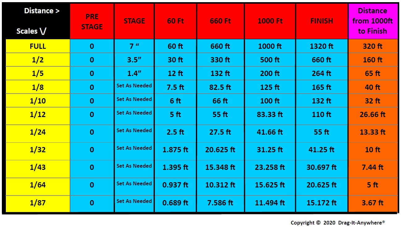
If you are not sticking to correct track lengths and have an odd Track Length, then you need to use this formula to figure the correct placement of the 1000ft sensor behind the Finish sensor.
USE 0.24242 x your custom Track Length. Example I am running 1/24 scale and only have room for 40ft not 55 ft so to calculate the 1000ft sensor position from the BACK from the FINISH sensor use: 40 x 0.24242 = 9.6 ft back from Finish Sensor.
