WIRELESS RACING TRACK SENSOR SYSTEM®
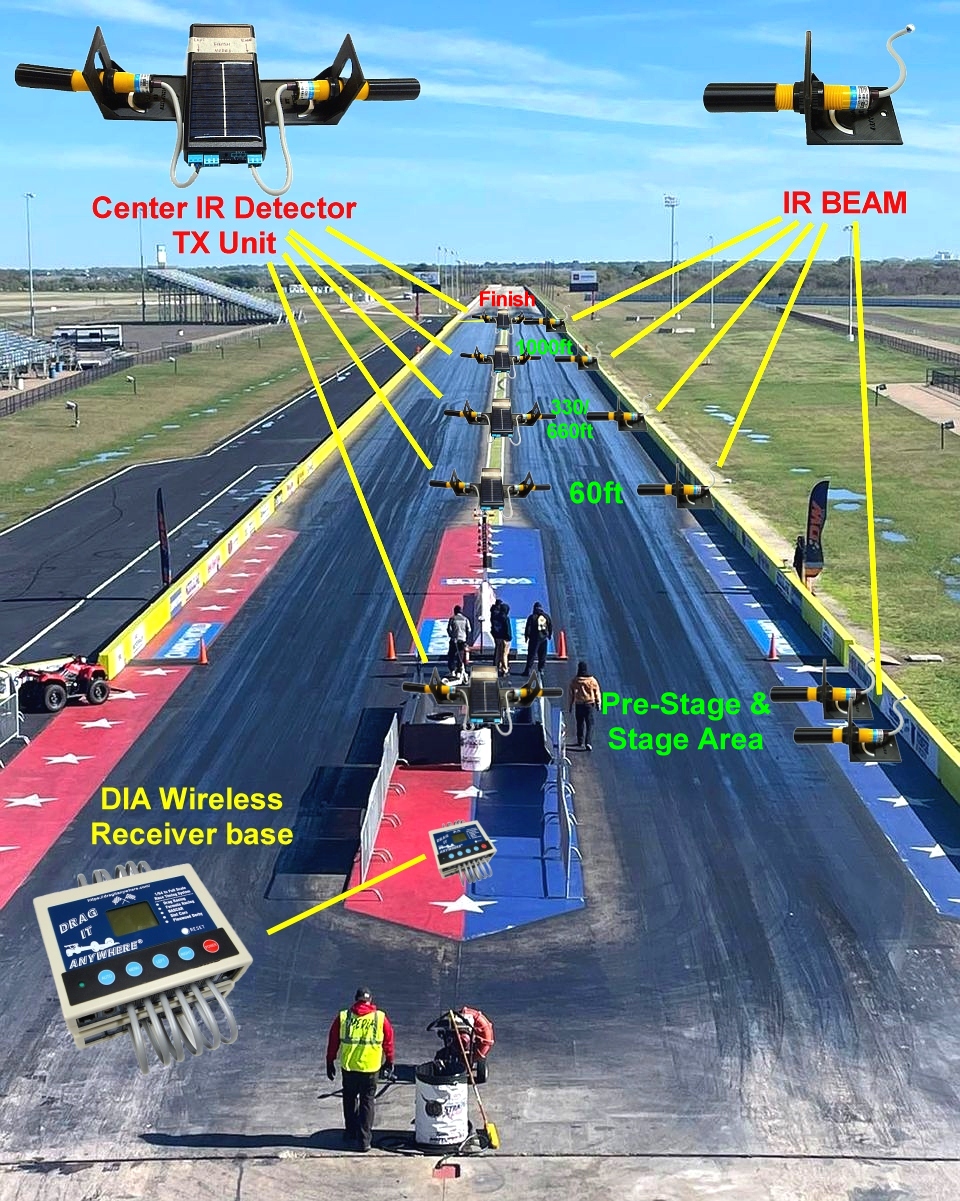
(The DIA crew has developed the Worlds ONLY Wireless Racing Track Sensor System®. Simple to use for anyone needing to track Times and MPH for Drag Racing, Lap Racing, RC & No-Prep Racers and more. Our proprietary designed system incorporates a 3-9 VDC 80mA Draw power system allowing the sensors to have a full day of racing action. Our Center Tract IR detectors and TX Sending unit incorporates a small Solar Panel to charge the batteries keeping your Transmitter going. With a Low Frequency 433MHz signal, the Wireless Transmitter is able to send instantaneous data base to the Main Wireless Receiver Base which connects to the main DIA unit. the Base unit needs no added power supply as it is powered by the DIA unit itself.
In order to use the Wireless Racing Track Sensor System®, you must have a Center Transmitter unit for each IR sensor Detector you wish to track. Designed for Pre-Stage, Stage, 60ft (6ft), 660ft (66ft), 1000ft (100ft or 120ft), & Finish Sensors (132ft) (Using 1/10 Scale as example). You must use a minimum of Pre-Stage & Stage Sensors and a Finish Sensor for the unit to record RT-ET-MPH/KPH. You have the option of adding the 60-330/660-1000ft-Finish sensors. Another amazing feature of the WRTS is that it allows you to use both Wired and Wireless Sensors at the same time. Meaning you can use wired Pre-Stage & Stage sensors and also Wireless Sensor mixed.
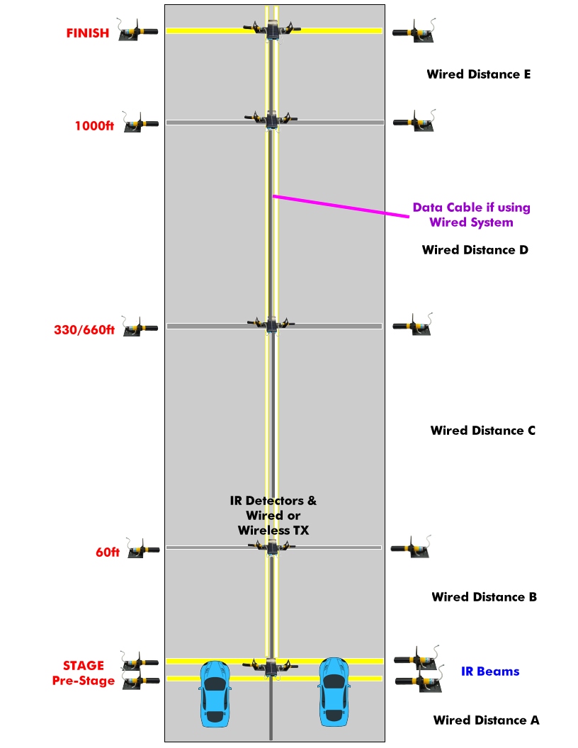
See the below Picture showing where we recommend Sensor Locations on a Standard Drag Track.
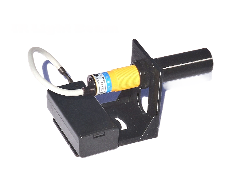
IR BEAM UNIT 9vdc
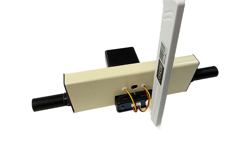
The IR Beam sits on the Outer side of the race track and is powered by a 9vdc Battery (recommend Ni-Mh Rechargeable). The Black Shade is normally placed on the IR Beam to help focus the IR forward and keep any sunlight reflections from interfering with the beam. Its up to the purchaser to determine how they wish to mount the IR beam to keep it in place on their track. We recommend mounting the beam to a small 1/16″ painted board to keep level and sturdy. The Beam can be adjusted Up/Down-Left/Right to best detect the Wheel or Body of the passing car. Some track surfaces may have a reflectivity to them, so adjust the beams by tilting the back up/down to have the IR detector best see the IR beam.
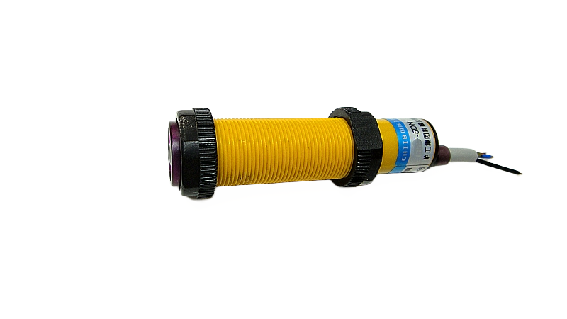
IR Detector Unit
The IR Detector unit is powered from 6-36 vdc. If plugging into our Wired Racing Track System®, then the Detector is powered by 12vdc, if plugging into our Wireless Racing Track System® then the power output is 8vdc. This Detector will detect the IR beam when an object blocks the IR beam and will send a HIGH signal output. The Wireless TX unit will send that High signal to the receiver base unit then to the DIA to record the cars Time when passing the sensor. In order to determine the MPH/KPH speed of a vehicle, you need a speed trap. This is done by placing a sensor at the 1000ft to Finish section. If running a 1/8 mile track see our sensor location placement page for correct placement of sensors. There is a JST connector on end of cable to plug into our TX Transmitter unit. If only using a Stage and Finish Sensor, then the DIA unit will use: Distance / Time to calculate a estimated ET MPH/KPH speed.
Wireless Racing TX Base Unit
The Wireless Transmitter Base Unit is powered by 2 x AA batteries with only a 80mA draw. The added Solar panel will keep the batteries topped off providing full sun is available. The unit will still give 8 or more hours in the dark. The Wireless Transmitter unit will send the detected HIGH signal from the IR Detector unit and encode that signal with a priority frequency to the Wireless Receiver Base unit then to the DIA main unit to record the Vehicles passing the sensor. Each Wireless Transmitter Base unit has its own priority selected frequency so no two units will interfere with one another. The WTBU has 2-JST mini connector ports for both Left & Right lanes. Its up to the owner to determine how they wish to mount the WTU on their track.
Wireless Racing Receiver Base Unit®
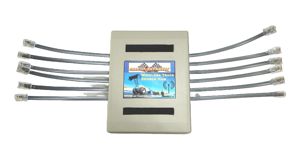
The Wireless Receiver base Unit® is powered the moment you plug any of the 12 available channels data cables into the main DIA unit. It will detect the wireless signal sent from the Wireless Transmitter Base unit on the track. You can use from 1 to 12 channels. Do not plug any sensors into this unit, it is designed only to output a HIGH or LOW signal from the Wireless TX units. It will detect from 1 to 12 TX signals. It mounts to the Underside of the DIA main unit with 2 small Velcro strips to secure in place.
DATA CABLE IF WIRED
To the right is a guide for laying out the Wireless and Wired System. For a Wired system you need Data Cables from each Sensor Shield. The DISTANCE A-B-C-D-E will tell you the needed length of Data Cable between each Sensor Shield. See chart for you scale. Most packages will come with the correct length needed.
